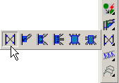
To draw a wind bracing, we activate the icon Wind bracing in the Parabuild toolbar.
A dialog box appears which allows us to choose one of the wind bracing types:
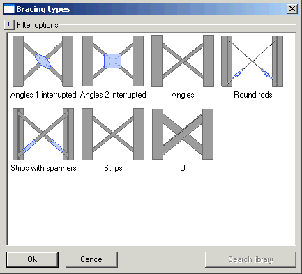
Select the desired bracing type and click on Ok.
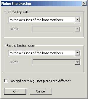
Now a dialog box appears with which we will determine the position of the wind bracing:
In order to draw a wind bracing, Parabuild needs two model lines on which to draw the two members. These are two intersecting lines that are drawn in the plane determined by the axis lines of the two base members. The start point of these lines is determined by a start point on the line and an offset. The end point of these lines is determined the same way.
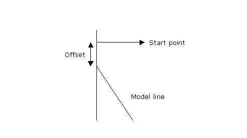
The standard value for the offset is 500. This value can be changed in the Bracing dialog box that is shown at the end of the command.
The start point at the top and the end point at the bottom can be determined as follows:
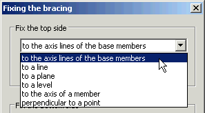
to the axis lines of the base members
This means on the start and end of the axis lines.
to a line
The line has to intersect with the base members.
- For a symmetric bracing, the start point is the intersection of the line with the axis of the first base member. This intersection point is used for both left and right.
- For an asymmetric bracing, the left start point is the intersection to the left, the right start point is the intersection to the right.
Attention!
- In case the line extends beyond the length of the base member and there is no real intersection, then Parabuild will use the apparent intersection of the line with the prolonged member axis. In this case, the gusset plate connection(s) might be drawn outside of the members in the air.
- In case the line is not drawn in the same plane as the plane of the bracing and thus a there is no real intersection, then Parabuild will project the line to the plane of the bracing to obtain the intersections.
to a plane
The same procedure as with lines, but in this case the intersection of the plane with the members axis is used.
to a level
The same procedure as with planes, but the difference is that these planes are always horizontal. This option therefore cannot be used for bracings in the roof.
to the axis of a member
The same procedure as with lines, but in this case the axis of the member you will select will be used.
perpendicular to a point
We can select a point (for example a point of a plate). The start point is then determined by projecting the point perpendicular to the member axis.
Top and bottom gusset plates are different
When you activate this option, Parabuild will show you the gusset plate selection dialog box twice. The first time for the top gusset plates and the second time for the bottom gusset plates
If this option is deactivated, the gusset plate dialog box will be shown just once and all four gusset plates will be the same.
When you click on Ok, the following prompts will show on the command line:
Select the left profile on the side where the bracing should be placed:
and
Select the right profile:
We select the backside of the flange of the member, on the side of the bracing
Depending on the selected options, we are also asked to select line(s), member(s), plane(s) or point(s).
Hereafter the Gusset plate connections dialog box appears.
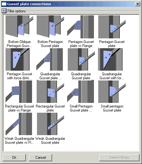
We choose the desired gusset plate and click on Ok.
Now the dialog box Connections for the middle of the bracing appears:
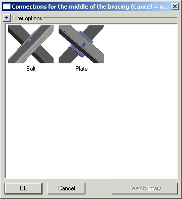
We choose an option and click on Ok.
Now Parabuild draws the wind bracing.
The previous prompts are repeated so that you can draw the same bracing on other locations. Press <Enter> when you have drawn enough bracings.
The Bracing dialog box now appears
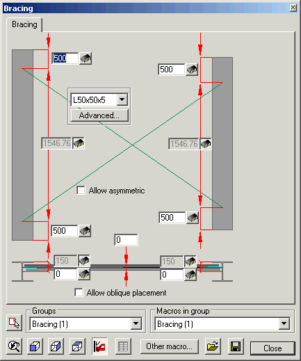
We can:
• Change the offset at top and at bottom. Only the values to the left apply because Parabuild has drawn a symmetric bracing. If we activate the Allow asymmetric checkbox, the values to the right will apply too.
• Change the member section by using the drop down tool.
• Choose another section type by using the Advanced... button. Warning: if you change something using this tool, then the gusset plate connections will likely become corrupted. In this case you should redraw them.
• Change the horizontal position of the wind bracing. This is possible by changing the position of the bracing axis relative to the member axis or the member edge. Only the left values apply. If you activate the Allow oblique placement checkbox, then the right values also apply.
Remark
This last setting gives us the possibility to draw a bracing between members whose axes are not aligned.
Attention
The gusset plates that Parabuild has drawn are only suggestions and should be reviewed to make sure the dimensions adhere to the load calculations.
The gusset plates can be modified individually with the Review macro command on the 4 smaller spheres.